是时候表演真正的技术了,我是怎么测电源的v1.8
A major goal of this website is to provide quality and reliable power supply unit (PSU) reviews. As a computer system component, similar to the CPU, the PSU also has its technical specifications and performance measurements. We believe that most readers of this article understand the important role that PSU plays in computer system. In order to make it easier for our readers to “digest” the reviews, it is necessary to have a user manual as the guidance, so we have it here. In this article, we will introduce the equipment and methodology we used, to help the reader, you, to establish a basic concept for understanding each technical specification and how does these terms affect the operation of the power supply system behind their measurements.
Our Equipment
Good equipment is the cornerstone for delivering accurate reviews. Every computer component has a suitable testing software and/or instrument, for example, the CPU and GPU can be tested with some benchmark software. But this becomes much more complicated when it comes to test PSU. In addition to having the proper knowledge of electronics, expensive and precise external electronic load and other instrumentations are required to comprehensively and accurately test various performance measurements.
The Chroma power supply test system is widely used by manufacturers in the PSU industry in their R&D, testing, and production processes, as well as Intel’s testing laboratory. The Chroma 6000 ATS was used for our early reviews. Starting with the EVGA SuperNOVA 1600 G2 reviewed at the end of 2016, we upgraded to the more advanced Chroma 8000 SMPS ATS system.
Since December 2019, another set of Chroma 8000 test system has been added and used together with the previous set of Chroma 8000, the equipment strength has reached a new level.
The programmable high-performance Chroma testing system can simulate various input and output states on the PSU under test, then we use appropriate instruments to measure different testing subjects. The electronic load module is the key component of this system, it simply determines the maximum power of PSU that can be tested. The electronic load module in our Chroma 8000 system consists of nine 63640-80-80 programmable DC electronic load (400W each), two 63630-80-60 programmable DC electronic load (400W each), and one 63610-80-20 (100W ×2), which allows us to have up to 4400W of load, two sets are up to 8800W load capacity.
In 2023, our main testing system added a Chroma 63206A-150-600 6kW single-channel high-power high-speed electronic load for ATX 3.0 projects. The total loading capacity of our main testing system is now 10,400W.
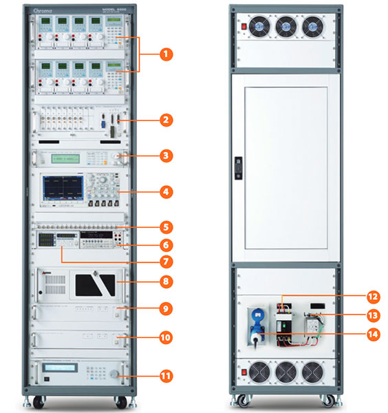
Our Chroma 8000 system also includes one Chroma 66202 digital power meter, one Agilent 34401A digital multimeter, one Chroma 61605 AC source (4KVA), one Chroma 80611 timing/noise analyzer, one Chroma 80612 OVP/short circuit tester, one Chroma 80613 ON/OFF controller, and an industrial PC.
Our external instrumentations include the following: one Tektronix MDO3014 oscilloscopes, and one Tektronix MSO44 oscilloscopes to analyze ripple, hold-up time and other subjects; one Suwei SW826 non-contact tachometer (resolution: 1RPM/min) to measure speed of fans; one FLIR One Pro thermal camera (accuracy: ±3°C or ±5%, resolution 0.1°C) to capture thermal images.
With the help of these expensive toys, we are able to perform the comprehensive test in accordance with the “Desktop Platform Form Factors Power Supply Design Guide” developed by Intel, which includes the often said “Intel ATX12V” specification.
Performance, Specification & Methodology
We will introduce each specification and methodology based on the structure of our PSU reviews. The test methodologies reference to “Intel Desktop Platform Form Factors Power Supply Design Guide”, which is a common guideline for R&D, production, and testing in PSU industry. The test program is developed by our tester “fc (fcpowerup)”.
Our PSU reviews are structured as follows:
1.Conclusion & Rating
2.Packaging, Contents & Exterior
3.Teardown & Component Analysis
4.Performance Tests
4-1. Voltage Regulation
4-2. Efficiency
4-3. No Load & Light Load
4-4. Fan Speed & Temperature
4-5. 5V Standby
4-6. Cross-Load Tests
4-7. Ripple & Noise
4-8. Inrush Current & Hold-Up Time
4-9. Dynamic Tests
5. FCP Graphics Compatibility Certification
1. Conclusion & Rating
The content replaces the previous introduction chapter, introduces the market background of product appearance, performance, positioning, price, quality and after-sales, etc., and evaluates product performance, work noise, material quality, whether it passes FCP graphics card compatibility test certification, etc. to sum up.
1. Introduction
Introduce the market background and market positioning of the brand and PSU itself.
2. Packaging,Contents & Exterior
Introduce and analyse the packaging, exterior design and build quality, cables, and other accessories.
3. Teardown & Component analysis
Disassemble the PSU to examine and analyse the interior design and components.
4. Performance Tests
Please see the detailed introduction in the next section.
5. FCP Graphics Compatibility Certification / FCP Gaming Ready Certification
Subsequent we will add a separate introduction article, mainly for the power compatibility test of the current high-power graphics card, build a PC game platform, use the graphics card for testing, including large 3D games and mainstream 3D test procedures, test whether the power supply can run safely and reliably. .
5. Conclusion & Rating
Give conclusion and rating according to the PSU’s exterior design, performance, build quality, acoustic noise, market positioning, price, and warranty.
Performance Tests in Details
4-1. Voltage Regulation
Different hardwares in computer request different operating voltages, usually CPU and graphic cards use +12V, motherboard and hard drive use +5V and +3.3V. Intel has clear requirements in their ATX12V specification: at all loads, the regulation ranges of +12V, +5V, +3.3V and +5VSB shall always remain within ±5%, and the regulation range of -12V is ±10%. Since current computer system has little use of -12V, -12V output is optional.
Beside the Voltage Regulation in Intel ATX standard, we also test Load Regulation in our reviews.
Voltage Regulation refers to the maximum deviation of the voltage from the standard value over the entire load range. Generally, the factory setting of voltage output will be slightly higher than the standard voltage to offset the transmission loss along cables.
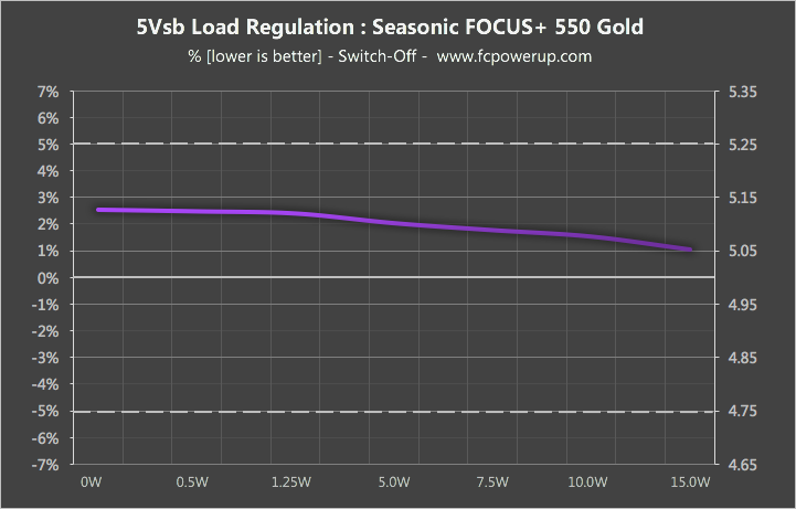
Load regulation refers to the changes of output voltage depends on loads over the entire load range. The smaller the variation, the stronger the voltage stability.
For example, the following graph shows the 5VSB of a PSU. Its standard voltage is 5V, the maximum measured voltage is 5.118V, the minimum measured voltage is 5.074V. Thus, the calculated maximum voltage deviation is 2.36%, and the load regulation is 0.88%.
4-2. Efficiency
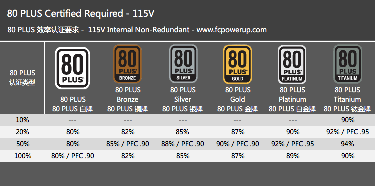
Common efficiency certifications include Blue Angel, ENERGY STAR, and 80 PLUS. Especially 80 PLUS, which has affected the entire industry in the past decade, is already the benchmark for PC PSU. The following chart is a simple demonstration of 80PLUS requirements, and we will have an article to talk about 80PLUS in detail in the future In “What is 80 PLUS, can you replace the 80 PLUS Gold Power Supply with the 80 PLUS Titanium Power Supply to earn the electricity bill cost back? “In this article, I have introduced this certification in detail.
Our efficiency test is different from other common certifications such as 80PLUS, which based on percentage load of rated maximum power. We test efficiency in fixed steps of load as the following table to cover both light loads, typical loads, and heavy loads and match the actual usage scenarios. Readers can find the corresponding power usage according to their hardware configuration. The efficiency is tested in both 230VAC 50Hz and 115VAC 60Hz.
The testing results are included in the “Input & Output Test” table, and are also display as efficiency curve.
Intel ATX12V specification has efficiency requirements for 20%, 50%, and 100% loads are 65%, 72%, and 70%, respectively. These requirements are easy to achieve for current mainstream PSUs.
4-3. No-load & Light Load Test
No load test measures the power consumption of PSU itself with zero output. We test the idle power consumption by shorting PS-ON and GND to turn the PSU on without having any output load. The PSU should has no damage or hazardous condition in the situation.
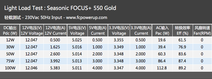
Light load test examine the performance of PSU when the PC is idle with desktop or when it is lightly used. We evaluates the voltages, efficiency, fan speed of the PSU in 5 load states: CL1 (approx. 12W, refer to 4.5 Cross-Load section), 30W, 50W, 75W, and 100W.
4-3. Fan Speed, Noise, Temperature
Fan speed is tested over the entire load range.
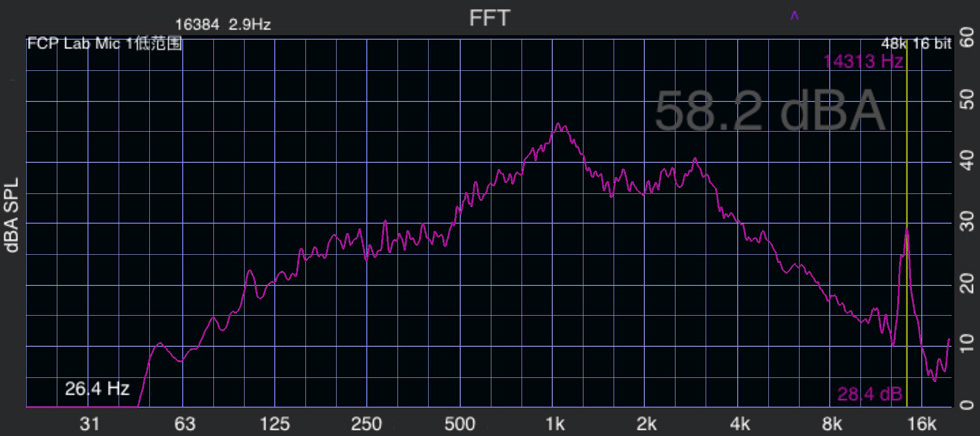
On June 1, 2020, three noise tests were added, namely 100W desktop application, 400W game mode, corresponding to the full load mode of the power supply. The power supply under test uses a zero-noise resistive load. In a low-noise environment, the specified power is output for more than 10 minutes. After the fan speed stabilizes, the power supply noise is measured at a position 10 cm away from the power supply air inlet.
After generating the FFT spectrogram, you can display the noise value (A-weighted) of the power supply, and you can analyze the high-frequency noise frequency and amplitude between 10kHz and 20kHz, that is, determine whether the power supply has high-frequency howling.
Temperature is captured by thermal camera after the PSU is fully loaded with 230VAC input after 10 minutes.
4-4. 5V StandBy
We test 5VSB according to the requirements of Intel ATX12V specification v2.3 and ErP Lot 6 2013 regulation. Intel ATX12V specification v2.3 requires the efficiency of 5VSB must be greater than or equal to 50%, 60%, and 70% at 100mA, 250mA, and more than 1A loads, respectively. ErP Lot 6 2013 regulation requires the power consumption to be less than 0.5W at 0A output and the efficiency of 5VSB must be greater than 45% at 45mA.
Currently we test 5VSB performance according to the following current load table.

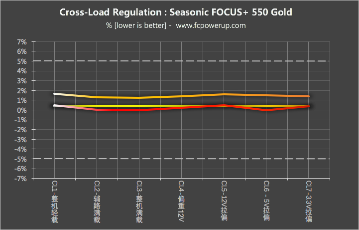
4-5. Cross-Load Test
The cross-load test takes ideas from Intel ATX12V specification v2.4 and SSI EPS12V Power Supply Design Guide v2.92, and combines the concepts of high-end platforms and low-power platforms.
We design seven states for cross-load test:
CL1 – Light Load: Test the voltage stability and efficiency at very low total load.
CL2 – Focus on +5V/+3.3V: Set +5V, +3.3V rails with maximum load and +12V rail with light load, to simulate the simultaneous startup of multiple hard drives.
CL3 – Heavy Load: Set +12V, +5V, +3.3V rails with maximum load, to simulate heavy total load.
CL4 – Focus on +12V: Set +12V rail with maximum load and +5V, +3.3V rails with light load, to simulate overclocking or gaming with single SSD.
CL5 – 12V Max: Test the performance of extreme case where +12V rail is at maximum load and +5V, +3.3V have no loads.
CL6 – 5V Max: Test the performance of extreme case where +5V rail is at maximum load and +12V, +3.3V have no loads.
CL7: 3.3V Max: Test the performance of extreme case where +3.3V rail is at maximum load and +12V, +5V have no loads.
The cross load mainly examines the stability of the output voltage. Within the range of ±5% required by the Intel ATX12V specification, the smaller the voltage deviates and load regulation, the better the accuracy and stability.
4-6. Ripple & Noise
The output voltage fluctuates like the water ripple when observed with an oscilloscope. Ripple and noise is the AC component that lay on the DC output of the PSU. A part of ripple and noise is the residual AC component after rectifying and filtering, another part is the ripple and switching noise generated by the transistor in the circuit. Excessive amounts of ripple can interfere with digital circuits and affect the stability of the circuit.
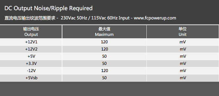
According to Intel ATX12V specification v2.52, the maximum output ripple and noise (p-p) is 120 mV for +12V, 50mV for +5V, 50mV for +3.3V, 120 mV for -12V, 50mV for +5VSB.
Our ripple test focus on +12V, +5V, +3.3V, and +5VSB, and does not test -12V. We follow the Intel ATX12V specification to connect the decoupling capacitors in parallel to the measuring points on fixture, and use an oscilloscope with 20 MHz of bandwidth to measure.
We test ripple and noise with seven states: 50W to simulate idle with desktop, 100W to simulate daily use, 300W to simulate gaming with single graphic card, maximum total load and maximum load of each rail (+12V, +5V, +3.3V) to test the performance under stresses. Usually the ripple is the largest when the PSU is at maximum load.
4-7. Inrush Current, Hold-Up Time
Inrush current
Inrush current is the instantaneous maximum input current drawn by the PSU at turn-on. Because the PFC capacitor needs to be quickly charged, the inrush current is considerably larger than the normal operating current. The smaller the inrush current, the better the performance. Excessive inrush current can damage components in PSU, such as the fuse, NTC thermistor, bridge rectifier, and AC switch.

Rise Time
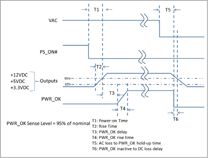
Mainly to test whether the T2 time in the Intel ATX12V specification boot sequence is in accordance with the Intel specification is 0.2~20ms. If it is not in this range, the boot may not be lit. Use the full load state to power on, use the oscilloscope to measure the voltage for overshoot, mainly to solve some users’ concerns that the power supply may damage the motherboard, graphics card and other accessories.
Hold-Up Time
Hold-up time is the time that the output voltages stay within required ±5% range after loss of AC input. According to the newest Intel ATX12V specification v2.52, the T5 (AC loss to PWR_OK hold-up time) must be greater than 16ms, in other words the PSU must be able to maintain PWR_OK (Power Good) signal more than 16ms after loss of AC source. Also T6(PWR_OK inactive to DC loss delay) must be greater than 1ms, which means the PSU must be able to keep DC output more 1ms after the PWR_OK signal stopped to keep other hardware running. In short, after loss of AC, PWR_OK signal remains > 16ms, voltage of DC output such as +12V/+5V/+3.3V remains > 17ms.
Sufficient PWR_OK hold-up time (T5) means that loss of AC within 16ms or switching to the uninterruptible power supply (UPS) will not cause the computer to shutdown or restart. Likewise, the DC voltage hold-up time (T5+T6), which is longer than the PWR_OK hold-up time, guarantees other hardware have time to take appropriate procedures, such as retracing the head in hard drives and power loss protection of SSDs.
The test setup for hold-up time is at maximum load with 264VAC input.
4-8. Dynamic Test
The above static test methods are designed to simulate the various conditions of the PSU when the computer power consumption is in a steady state. Assume that a computer steady consume 300W power when it is at maximum load, according to our test result, Corsair RM650x v2018 has 12.038V output for +12V rail, 9.2mV of output ripple, and 0RPM of fan speed at this moment.
However, in reality, the power consumption of the computer changes at every moment. For example, the load of CPU rapidly increases, causing the power limit to change from PL1 to PL2 and keep it for 10ms; When playing game, the power consumption of the graphics card may reach 300W or even higher, for a few milliseconds.
Traditional static test methods do not consider the dynamic changes of power load. Due to factors such as line compensation, resistance of components and input impedance, the output voltage of the PSU generally decreases as the load increases. When the load is removed, there is a process for the output voltage to recovery to steady state.
According to the following graph, when the load shift from I/R-1 to I/R-2 (called “load transient”), the output voltage of PSU drops from Vs-1 to Vs-2, like a step down. It takes time for the PSU to response to change of load, as a result, there actually is a process of “overshoot/undershoot – recovery”. During this process, the peak voltage change is usually larger than the regulated output voltage in magnitude. In other words, when the load increases from I/R-1 to I/R-2, the output voltage first drops to a lower voltage Vpk-1, and then gradually rise up to the steady voltage Vs-2. Conversely, when the load drops from I/R-2 to I/R-1, the output voltage will rise from Vs-2 to Vs-1. This process also has a higher overshoot voltage Vpk-2 than Vs-1.

DC Output Transient Test in ATX12V specification requires the load changes from 50Hz to 10kHz, and the output voltage keeps within ±5%. Currently we only test +12V which’s load transient usually is large in magnitude and high in frequency, and ±5% for 12V is ±600mV.
Our test first verify that the PSU should not shut down, restart, or fail. Then we measure the peak voltages for overshoot and undershoot. Beside that, we also measure the time that the PSU needs to regulate the voltage after load transient occurred Tr-1 and Tr-2.We call them the voltage recovery time (or voltage rebuild time), and we believe voltage recovery time directly reflects the dynamic performance, although Intel’s ATX12V specifications has no requirement of such time.
Based on the current CPU and graphic card in market, our dynamic test stage-2 uses following setups:
12V2: 1A ↔ 9A, step size 8A, rise rate 1A/μs, in equivalent to the mean difference between the continuous current and peak current of the CPU defined in ATX12V 2.52.
12V3: 1A ↔ 13A, step size 12A, rise rate 1A/μs, in equivalent to a 150W graphic card switch cramp between maximum load and idle.
12V3: 1A ↔ 13A, step size 12A, rise rate 1A/μs, in equivalent to a 150W graphic card switch cramp between maximum load and idle.
For small and medium wattage PSU:
12V2 and 12V3 are loaded synchronously, simulating the simultaneous operation of CPU and graphics card. The accumulated basic Load of 12V is 3A and the dynamic Load is 20A/240W, which is equivalent to bringing a mid-end graphics card to play games or run Benchmark.
For 1kw+ wattage PSU:
12V2, 12V3 and 12V4 are loaded synchronously, simulating the simultaneous operation of CPU and graphics card. The basic Load of 12V is 4A and the dynamic Load is 32A/384W, which is equivalent to bringing a high-end flagship graphics card to play games or run Benchmark.
We test dynamic performance with 5 different changing rate: 10Hz, 50Hz, 100Hz, 1kHz, 10kHz. We chose 50Hz and 100Hz as the main test object to show the performance difference in the review. Normally 1kHz and 10kHz will not be mentioned, unless important problem, like the overshoot/undershoot voltage exceeding the requirement, occurs.
Take the Corsair RM650x v2018 as an example for dynamic test:
@100Hz
Tr1:2.5ms,Vpk1:-168mV;

Tr2:2.5ms,Vpk2:252mV;

By default, the included cables are used in the test. The 12V cables come with Corsair RM650x v2018 feature inline capacitors. In dynamic test, neither shut down nor restart has occurred, and the output voltage does not exceed ±5%. The average voltage recovery time is 2.5ms, which is slightly slower than medium level in our current data collection.
Currently, dynamic test result is not being rated.
12V Large Dynamic Load Test
Considering recent trends in power consumption and updates to Intel’s standards, some readers might feel that our dynamic test range is no longer sufficient. Indeed, the standard was designed in 2016 when CPUs and GPUs had lower power consumption, and mainstream power supplies were mostly around 650W. At that time, using a dynamic load range of 12V 3A↔35A/36W↔420W for performance comparison was appropriate.
Therefore, in our 2025 review of the Thor 3 1200W, we introduced a larger dynamic load range for testing. Below is an example:
Test Range (Step Size):
70% of the rated power: 0↔70%, 30↔100%
Test frequencies: 25Hz, 50Hz, and 10KHz
Slew rate: 1A/μs
For some premium models, we apply a more rigorous 85% dynamic load range:
0↔85%, 15↔100%
Test frequencies: 25Hz, 50Hz, and 10KHz
Slew rate: 1A/μs
Test Results for the ROG THOR 1200W Platinum Ⅲ:
25Hz-0%~85%-0A~85A-Load Rise:
12V min: -520mV , Voltage recovery time: 900μs
25Hz-0%~85%-0A~85A-Load Drop:
12V max: 400mV, Voltage recovery time: 1.4ms
4-9. Protection Features
Protection function tests currently include Over Power Protection (OPP), Over Current Protection (OCP), and Short Circuit protection (SCP).
Over Power Protection (OPP): The power supply gradually increases the output power from near full load until the power supply fails to work in the protection state. Finally, the power supply must be able to cut into the protection state. If the power supply does not have OPP protection, it may blow up or damage other hardware.
Over Current Protection (OCP): A mandatory requirement for the Intel ATX12V specification. Current protection should be designed to limit the current to operate within safe operating conditions.
Over current protection schemes, where only the voltage output that experiences the over current event is shut off, may be adequate to maintain safe operation of the power supply and the system; however, damage to the motherboard or other system components may occur. The recommended over current protection scheme is for the power supply to latch into the shutdown state. PSU connectors, cables and all other components should not be melted or damaged prior reaching to the OCP trigger.
Short Circuit Protection (SCP): An output short circuit is defined as any output impedance of less than 0.1 ohms. The power supply shall shut down and latch off for shorting the +3.3V DC, +5V DC, or +12V DC rails to return or any other rail. The +12V1 DC and 12V2 DC should have separate short circuit and over current protection. Shorts between main output rails and +5VSB shall not cause any damage to the power supply. The power supply shall either shut down and latch off or fold back for shorting the negative rails.
example: This is the protection features test result of ASUS ROG Strix 750W Gold,No Load Operation and Surge & Inrush Protection can also be judged to be functional according to the above tests and disassembly.
| 保护功能测试 | Protection Features |
|---|---|
| 过流保护, OCP (Over Current Protection) | 12V: 86.5A (139.5%) 5V: 28.5A (142.5%) 3.3V: 28A (140%) |
| 过功率保护, OPP (Over Power Protection) | 1044.53W (139.27%) |
| 短路保护, SCP (Short Circuit Protection) | 12V: ✓ 5V: ✓ 3.3V: ✓ |
| 空载保护, NLO (No Load Operation) | ✓ |
| 浪涌保护,SIP (Surge & Inrush Protection) | MOV压敏电阻、NTC热敏电阻、继电器 |
This article is our PSU test equipment and methodology. We will continue to upgrade our equipments and improve our methodologies to match the evolving industrial specifications and user demands.
4-10. Current Harmonic Test
The primary test standard is IEC 61000-3-2/GB 17625.1: Limits for harmonic current emissions (equipment input current ≤16A per phase) for low-voltage electrical and electronic equipment. When operating, switch-mode power supplies inject harmonic currents into the power grid, potentially interfering with other devices on the same grid, such as causing lights to flicker or other appliances to emit noise. Using the relevant test items from the Chroma 8000 system, we measure compliance with IEC 61000-3-2 Class A and Class D limits. Passing the test means the harmonic current does not exceed the specified limits.
Example:
Class A, passed the test.

The above outlines our power supply testing equipment and methods. Intel, the rule-maker of the industry, periodically updates its specifications, so I will continuously update the testing equipment and improve the testing methods according to industry trends and user needs.
5.FCP Graphics Card Compatibility – FCP Gaming Ready
Version 1.7 has finalized the graphics card compatibility tests, incorporating ATX 3.0 testing items. For more details, please refer to “Epic Update: FCPOWERUP Standard 1.7 Adds ATX 3.0 Testing Items.”
Changelog:
Version 1.8, 2025-01-23
•Added 12V Large Dynamic Load Test.
•Upgrade equipment
Version 1.7, 2023-05-05
•Removed section 4.3 on light load. Subsequent sections are renumbered accordingly.
•Added 2% ultra-light load efficiency test in section 4-1.
•Added section 4-10, Current Harmonic Test.
•Added FCP Gaming Ready, integrating ATX 3.0 standard for graphics card compatibility, to section 5.
2020-06-01, Version 1.6
- Chapter 4-4, added noise test, and can analyze the frequency and amplitude of high-frequency howling of power supply.
2019-12-20, Version 1.5
- Add 80 PLUS Article “What’s 80 PLUS?” In 4-2. Efficiency.
- Add Another Chroma 8000 SMPS ATS system.
2019-08-14, Version 1.4
- Section 4.8 add the rise time test.
- Added 4.10 Protection Features test, including OPP, OCP and SCP Features test.
- The test method was updated from version 1.2 to version 1.4 on the same day, and the English version was also updated to version 1.4.
2019-08-14, Version 1.3
- NZXT E850 Review began to add the FCP graphics card compatibility test certification Beta (2019-07-25).
- ASUS ROG1200P Thor Review began to adjust the article chapter order (2019-01-25). The product introduction and rating and summary are merged and adjusted to the first page, so that the reader can see the conclusion on the first page.
2018-01-25
- Add English Version v1.2.
2018-11-24
- Add English Version v1.1.
2018-11-09
- Add English Version.
2018-11-08Version 1.1
- Add 4-9 Dynamic Test.
- 4-5 “ErP Lot 6 2013 regulation requires … the efficiency must be higher than 45% at 45mA.”
- 4-8 Inrush current use 264Vac input.











请教下有风扇有外壳的,红外热成像怎么能准确测量? 拆掉上盖会破坏风路散热条件。
即使是4年后,大魔王的测试方法的专业性依然没有人能超越,是真滴流批。
针对正文内容本菜鸡有一点小疑问,大佬有空能解答下就太好啦:
【4-9.动态测试】内容中,提到了部分硬件的瞬间功耗可能会非常高,那这个瞬间功耗会不会超出官方给出的最高TDP呢?12v1-12v4的表格中所设定的150w功耗,是否可以理解为“瞬时功耗能达到150w的显卡”,而非 “TDP为150w的显卡”?电源应对这个“瞬间功耗”的能力要比本身的功率过载能力更强一些吗?
@Fuwill: 产品一直在不断变化,主要是显卡和CPU,所以标准和测试方法也是在不断改进。
按Intel早期的动态测试要求,摆幅即加载在电源上的功耗,是不会超出电源的额定功率,以PSUDG1.43即2.52标准为例,12V2最高要求的幅度是85%的12V额定电流,12V3V4最高到80%。但到了ATX3.0,出现了超出电源额定功率的超载动态项目。
我设计的动态项目是比较早的,从2014年就用了类似的相对固定的负载,当时还没有对显卡的峰值功耗的研究内容。设定的动态负载是12V从4A到32A来回切换,有400W左右的跳变,相当于CPU再加上300W的显卡,这对于大部分电源来说是一个可以承受的动态测试功率范围,是一个适合用来衡量所有电源动态性能的标准。到了后来进行了显卡负载特性的研究之后,对CPU和显卡的工作模式理解更深入,我增加了显卡兼容性测试章节,有了更苛刻的动态过载测试。
好了,回到你的提问,这个项目的设计之初就认为TDP=150W的显卡,它的最大功耗、峰值功耗也是150W。实际上显卡的峰值功耗是可以达到TDP的2~3倍,Intel ATX3.0约束在3倍以内/100ms。电源应对小功率的动态负载,比如300W,显然是要比应对3倍300W的过载动态要从容得多,元器件不会工作在过载状态,输出的参数更容易合规。
@fcpowerup: 大概明白了,就是说其实各种电源在设计的时候,针对“瞬间功耗”和“过载功耗”是有两套标准的,区别主要在持续时间上?以目前ATX3.0为准的话这个“瞬间功耗”应该是TDP*3/100ms,而过载功耗可能是更低瓦数但更长时间这样子?
@Fuwill: 你说的瞬时功耗和过载功耗是一回事
@fcpowerup: 啊……那就是说一块OPP临界点在1000w的电源,就算是硬件的瞬时功耗也是没法超过这个数,超过了电源就会触发保护这样对吗?电源的功耗承载上限还是在OPP那边控制的。
@Fuwill: 非也,硬件的功耗是它自己的事情,电源约束不了它。电源有它自己的OPP参数,一旦硬件超出它的OPP规格就会保护。
@fcpowerup: 嗯嗯我就是这个意思,可能表达的有点问题…谢谢大魔王啦
一脸懵逼的进来,再一脸懵逼的出去。太专业了~,看不懂~
请问是否考虑增测市电对电源的影响?例如电压不稳或别的的情况?
我的xfx xtr550和漫步者的音箱插在同一个排插上,及时在桌面待机状态下,一旦对音箱进行插拔或开关操作,电脑就会黑屏死机,显卡负载灯熄灭。同样的cpu和显卡,换在另一台电脑上没有这个问题。电源还是使用的是鑫谷S7这种低端电源,插拔、开关音箱则没有问题。主板之前有出现过故障然后售后换新,回来问题依旧。
请问这是电源的单个质量问题可以售后,还是设计方面的问题呢?亦或者可能是主板设计问题?假如是电源设计问题,是否考虑增加相关测试呢?谢谢。
@迎风舞焰: AC部分有115V的低压测试和掉电保持时间的测试。一个音箱不至于让AC电压有巨大的波动,考虑是3.5mm上面有异常的电信号导致主板工作异常。
@fcpowerup: 发现问题了。我之前是音响一直连着显示器。当我音响的3.5mm接口从显示器上拔下来后,对音响进行开关,显示器会黑屏几秒钟再亮,但是电脑不会死机了。应该是这个原因吧。谢谢。
@fcpowerup: 发现问题了。我之前是音响一直连着显示器。当我音响的3.5mm接口从显示器上拔下来后,对音响进行插拔,显示器会黑屏几秒钟,但是会亮回来,电脑也不会死机了。应该是这个原因吧。谢谢。
@迎风舞焰: 电源厂商设计时就该考虑到客户的实际使用环境啊,一般测试条件都是比标准较苛刻的,纹波不超过VCC的5%。
@MasterLiu: 对音响拔插导致主板黑屏死机,有可能是主机板音频接口有静电释放问题。建议戴静电手环或接地线拔插测试一下
@MasterLiu: 发现问题了。我之前音响一直连着显示器,显示器连显卡。当我音响不连显示器的时候,对音响进行开关,显示器会黑屏几秒钟再亮,但是电脑不会死机了。谢谢。
这套设备太专业了,百万级的设备测电源,太牛了。
专业!
今天看travis分享的文章,惊喜,再一看设备,正点,这确实是亚洲第一了(哈哈)。
@卓克: 感谢卓老板支持!
F大,看完您的電供專業評測之後~我發現其他所謂的"專業"都弱爆了
请问F哥,你用的红外热成像仪是FLIR的哪一个型号?
@小猪下来: 上面有写的,FILR One Pro
@fcpowerup: 实在是不好意思
大佬和itocp有什么关系吗?我印象里如此专业的电源评测以前就只在itocp看过,以前他们甚至还自制了一个pci-e槽测功率的。但那网站好像作的没人了,我就再也没见过如此舒服的电源评测了,现在又发现这了,已圈粉
@wawa: 我以前是玩家堂版主,2012~2016年在超能网负责电源评测栏目。感谢关注!
买好电源之前一定要来这看看 做功用料 纹波低的电源 顺便想知道 16awg线材到底是否需要电容
@mngod123: 线端电容是用来弥补部分滤波或者动态特性的,跟线材粗细不相关
真专业 再也不会买到那些红星电源了 这网站真棒
马克,超能时期就很关注FC大佬的电源测试
很详细